Table of contents

- Installation Goal
- Sensor used: Dragino DS03 (LoRaWan)
- Sensor connection with the LoRaWan gateway
- General gateway configuration
- Sensor Addition
- Interpretation and sending of sensor data
- Introduction to Node-RED
- Decoding and Sending Data via Node-RED
- DS03A Decoding Script on the Wise-6610
- Data Storage Configuration in IoTEdge
- Physical installation of the sensor
Installation Goal
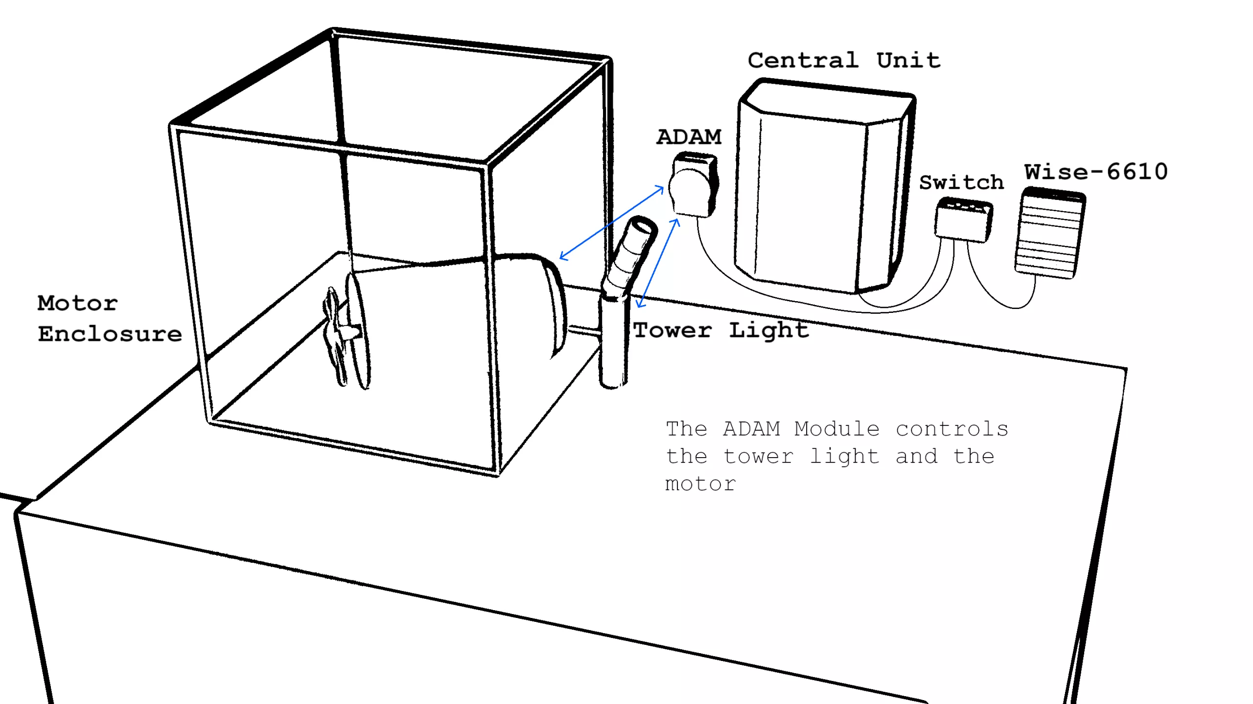
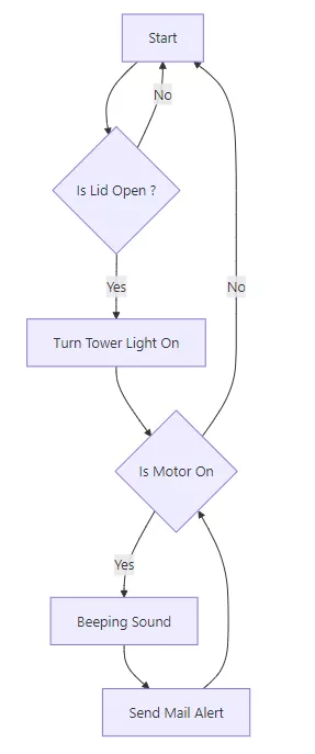
As part of the implementation of a security system for our test bench, we have chosen to use a LoRaWan sensor (see below) to detect the opening of the lid of our test cube. On the side, a diagram illustrating the expected behavior of the system.
In summary, our goal is to be notified every time the lid is opened, and to receive an alert if the lid remains open during the operation of the motor.
This alert will be generated by a sound signal, the sending of an email, and the display of an indicator on a dashboard. The sensor will communicate via the LoRaWAN protocol with our WISE-6610 gateway.
Sensor used: Dragino DS03 (LoRaWan)
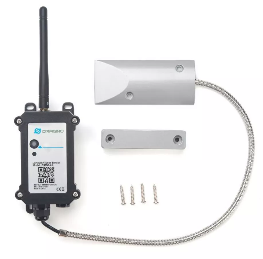
The DS03A is a LoRaWAN sensor designed to monitor the opening and closing of doors. It transmits key information such as the door status (open or closed), the duration of opening, as well as the number of openings, via the LoRaWAN protocol. We want to install it on our test bench to detect the opening of the motor cube.
Sensor connection with the LoRaWan gateway
The pairing procedure varies depending on the LoRaWAN gateway used. In this case, we will use the Advantech WISE-6610 V1 gateway. This pairing step will allow the gateway to establish communication with the DS03 sensor, enabling it to receive, read, and decode the messages transmitted by it.
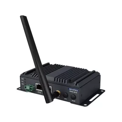
We are using version 1 of the WISE-6610 gateway (already installed on our bench), which is not the most recent. Although subtle differences may exist, the procedure as well as the general principles remain applicable for version 2 (or Wise-6610-EB).
General gateway configuration
In this case, we are using a largely preconfigured gateway. All that remains is to add our sensor to the list of devices.
To proceed, it is advisable to connect to the gateway via its local network to access the configuration panel, simply by opening the gateway's IP address in a browser. The default credentials are `root` / `root`.
To proceed, it is advisable to connect to the gateway via its local network to access the configuration panel, simply by opening the gateway's IP address in a browser. The default credentials are `root` / `root`.
The default credentials for the Wise-6610 v2 gateway are `admin`/ `admin`.
Once connected, in the menu `User Modules > LoRaWAN Gateway > Network Server > Settings`, it is essential to verify that the LoRaWAN network is indeed activated.
The configuration of the LoRaWAN network can then be adjusted via the dedicated page, accessible by connecting to port `1660` of the gateway (note that this port is modifiable).
Access to the LNS of the v2 is done via the menu `LoRaWan > Advantech LoRaWan Service`.
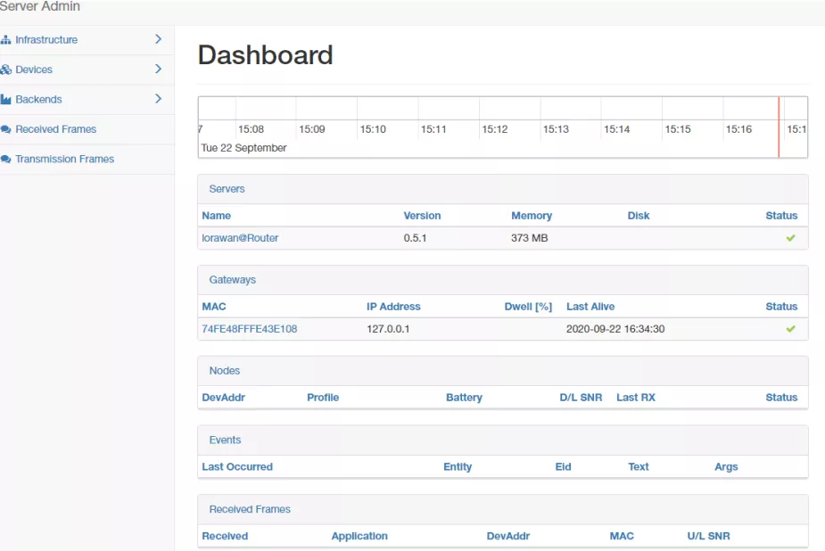
LNS Dashboard of the Wise-6610 v1
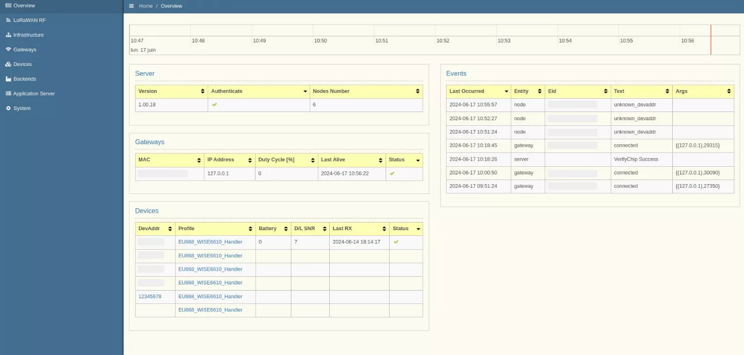
LNS Dashboard of the Wise-6610 v1
Sensor Addition
Our sensor operates in OTAA activation mode. To add it, simply open the menu `Devices > Commissioned`, then click the `Create` button.
In v2, this menu is accessible via `Devices > Create Device > Type : OTAA`
At this stage, several fields must be filled with information specific to the sensor. This data, unique to each device, is available on the sensor's label:
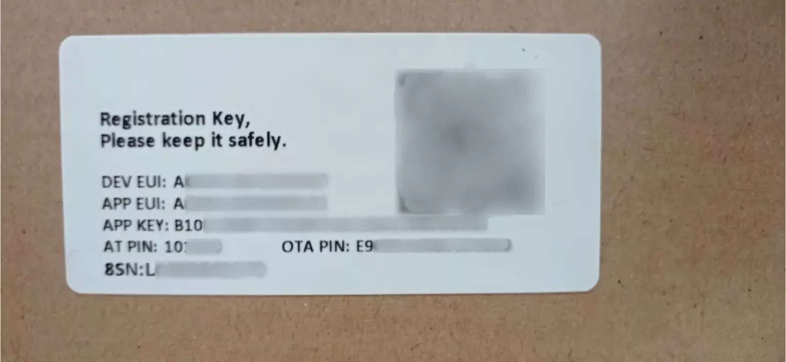
Once the fields are filled in, simply click the `Submit` button to add the device.
After turning on the sensor (by holding the button down for 3 seconds), it should automatically connect to the gateway. Its LED first lights up green for a few moments, then turns blue before turning off.
After turning on the sensor (by holding the button down for 3 seconds), it should automatically connect to the gateway. Its LED first lights up green for a few moments, then turns blue before turning off.
To check the connection, simply access the `Received Frames` (v1) or `Frames Traffic` (v2) menu, where the frames sent by the DS03 should appear.
Interpretation and sending of sensor data
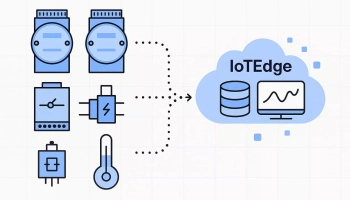
The DS03 sensor transmits its data in the form of hexadecimal strings. In order to store them intelligibly in our software IoTEdge, we need to convert them into a compatible format. IoTEdge accepts data in JSON format, sent via MQTT.
We will therefore proceed to convert the hexadecimal data into a JSON object containing clear and readable information. To do this, we will use the Node-RED tool, included in our gateway.
We will therefore proceed to convert the hexadecimal data into a JSON object containing clear and readable information. To do this, we will use the Node-RED tool, included in our gateway.
Introduction to Node-RED
Node-RED is a visual programming environment designed for data collection, transformation, and transfer. Based on a JavaScript engine, its interface consists of flows and connectable blocks, allowing for operations, sending and transforming data, as well as processing it flexibly.
We will frequently use the `function` block, which allows integrating JavaScript code directly into the Node-RED flow.
The transfer of information between blocks occurs in the form of JavaScript objects.
To access Node-RED on the gateway, simply go to port 1880 (by default) of the gateway by accessing the following URL: `http://{gateway IP}:1880/#`.
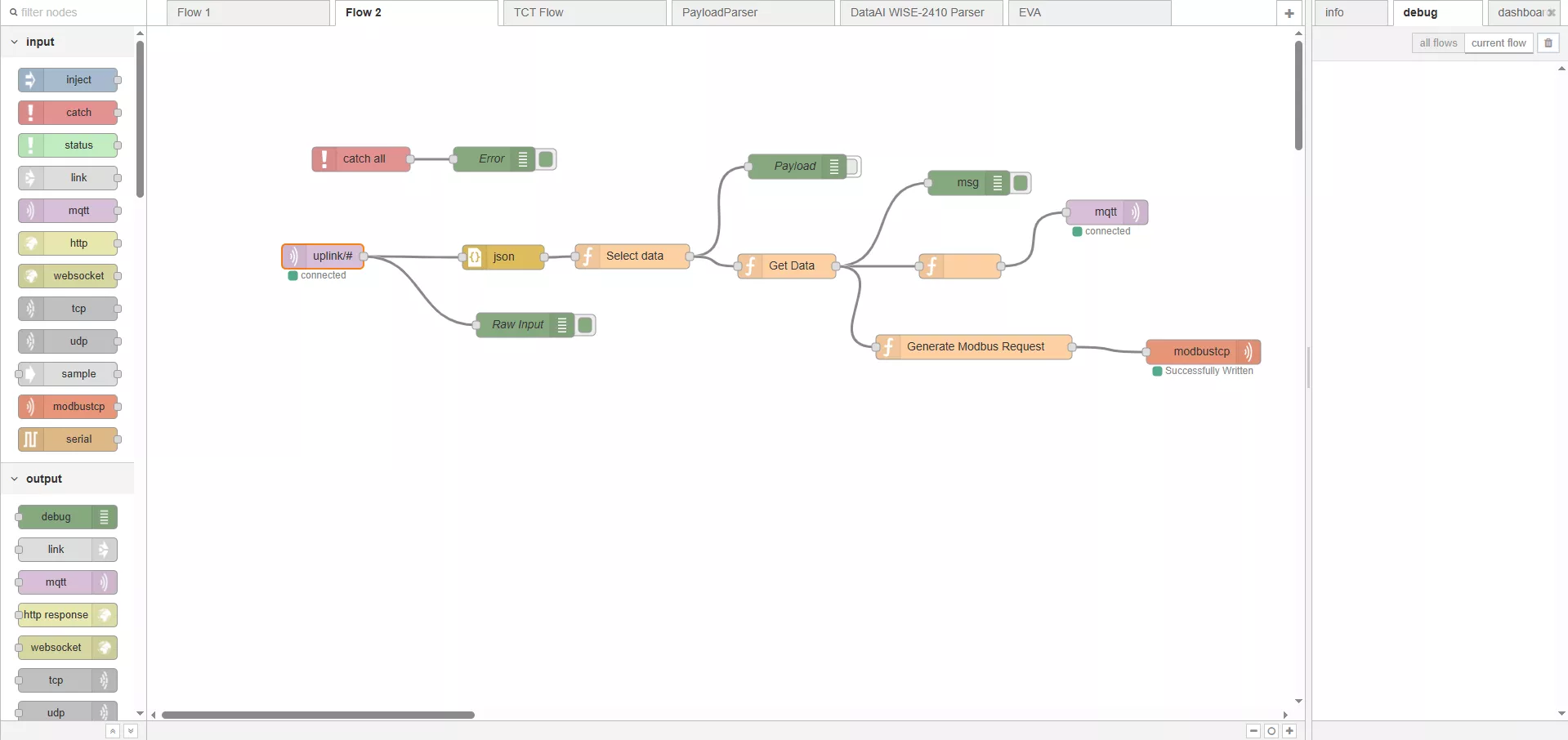
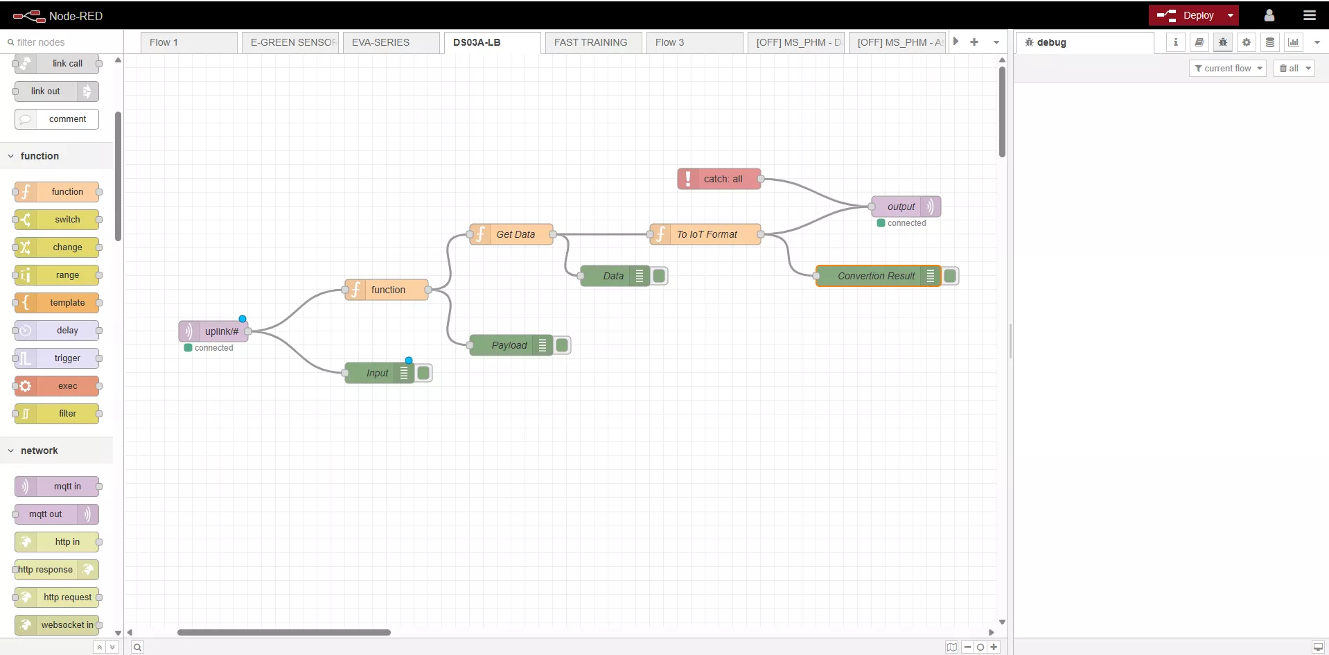
Screenshot of the Node-RED interface
If Node-RED is not already enabled, you should access the gateway configuration page (`http://{Gateway IP}`). In the left menu, then select `Customization > User Modules`.
In v2 `Application Tools > Node-RED > Settings`.
You will find a clickable link titled `Node-RED`, which will allow you to configure the tool. After clicking on this link, check the box `Enable Automatic Start`, then click `Apply` to validate the configuration.
In v2, check `Node-RED control`.
Decoding and Sending Data via Node-RED
The gateway receives a LoRaWAN frame and performs an initial processing, converting it into a JSON object containing the hexadecimal frame, signal quality, timestamp, and sensor ID. This data is then sent to an internal MQTT broker, which relays it to our Node-RED flow. This process takes place entirely internally within the gateway.
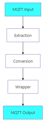
The designed Node-RED flow is simple and follows the plan next to it. The idea is to decode the message and then format it correctly to send it to IoTEdge.
The designed Node-RED flow is simple and follows the plan next to it. The idea is to decode the message and then format it correctly to send it to IoTEdge.
Some additional clarifications:
Input : The topic used for the input is a wildcard `uplink/#` allowing to receive data from all sensors connected to the gateway. If you want to restrict the stream to a single sensor, you should replace `#` with the DevAddr identifier of the sensor.
Conversion : The conversion corresponds to the step of translating the hexadecimal frame into usable data, according to the manufacturer's official documentation. Although a decoding script provided by Dragino is available online, it requires several adjustments to work correctly (see note n°1) and presents an incompatibility with the 6610-V1 gateway (the v2 also requires adjustments).
We will therefore use an alternative script (see below), specifically developed to ensure compatibility with the 6610-V1 gateway. You simply need to copy this script into the second function block of your Node-RED environment.
Wrapping : For IoTEdge to accept and interpret the data correctly, it must be structured according to the following format:
{
	"d":[
		{
			"tag":"Something:IoTEdge_Tag",
			"value":value
		},
		{
			"tag":"Something:IoTEdge_Other_Tag",
			"value":other_value
		}
	],
	"ts":"00000000000"
}
DS03A Decoding Script on the Wise-6610
//Ce script ne prend actuellement pas en charge le mode Dual Channel.
bytes = []

c = 0
while(c < msg["data"].length) {
    bytes.push(parseInt(msg["data"].substr(c, 2), 16));
    c+=2;
}

result = {}

if(msg.port == 2 || msg.port == 3) {
    //Statut d'ouverture/fermeture en temps réel et historique
    //Pour des raisons de simplicité, traduisez uniquement la première entrée des événements historiques.
    result["DOOR:COUNT_MODE"] = (bytes[0] & 0x08) ? "RES" : "FAC"; //RES : Depuis la réinitialisation / FAC : Depuis l'usine
    result["DOOR:TDC"] = (bytes[0] & 0x04) ? 1 : 0;
    result["DOOR:ALARM"] = (bytes[0] & 0x02) ? 1 : 0;
    result["DOOR:DOOR_OPEN_STATUS"] = (bytes[0] & 0x01) ? 1 : 0;
    result["DOOR:DOOR_OPEN_TIMES"] = bytes[1] << 16 | bytes[2] << 8  | bytes[3];
    result["DOOR:LAST_DOOR_OPEN_DURATION"] = bytes[4] << 16 | bytes[5] << 8 | bytes[6];
}
if(msg.port == 4) {
    //Configuration du capteur
    //Envoyé uniquement après un message de liaison descendant du serveur
    result["DOOR:TDC"] = bytes[0] << 16 | bytes[1] << 8 | bytes[2];
    result["DOOR:DISALARM"] = (bytes[3] & 0x1) ? 1:0;
    result["DOOR:KEEP_STATUS1"] = (bytes[4] & 0x1) ? 1:0;
    result["DOOR:KEEP_TIME1"] = bytes[5] << 8 | bytes[6]
    result["DOOR:KEEP_STATUS2"] = (bytes[7] & 0x1) ? 1 : 0;
    result["DOOR:KEEP_TIME2"] = bytes[8] << 8 | bytes[9]
    result["DOOR:ALARM_INTERVAL"] = bytes[10]
}

if(msg.port == 5) {
    //Statut de l'appareil
    result["DOOR:SENSOR_MODEL"] = (bytes[0] & 0x1B) ? "DS03A" : "Appareil inconnu";
    result["DOOR:FIRMWARE_VERSION"] = "${bytes[1]}";
    result["DOOR:FREQUENCY_BAND"] = "EU868";
    result["DOOR:SUB_BAND"] = 0x00;
    result["DOOR:BATTERY"] = byte[5] << 8 | byte[6];
}

output = {
    "d":[],
    "ts":"00000000000000000000000"
}

for(k in result) {
    output["d"].push({"tag":k, "value":result[k]})
}

output["raw"] = result

return output
From now on, the gateway transfers data from the sensor to IoTEdge, in the cloud.
Data Storage Configuration in IoTEdge
The transmission of data to IoTEdge occurs via the MQTT protocol. In order for IoTEdge to interpret them correctly, it is necessary to create a representation of the device within the platform. This entity will allow associating the received data with an identified device.
In IoTEdge, devices are defined as sets of variables representing the state of a sensor. Each device is based on a device model — the equivalent of a type of sensor — and its specific configuration is called device details, representing a concrete instance of this model.
We will now create a new device model. To do this, go to the IoTEdge interface, then access the Device Center > Device Model section.
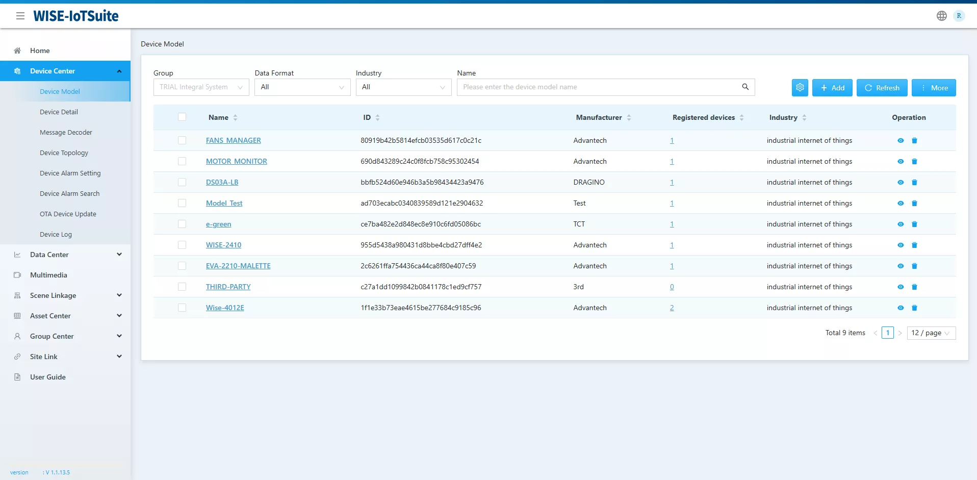
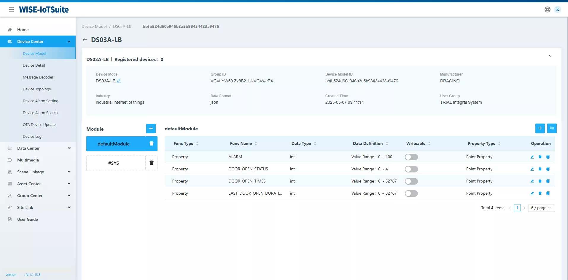
Then click on + Add to open the window for creating a new template. You should then define the variables exposed by the sensor, namely:
//The bools in IoTEdge are represented by {0, 1}, to be used in dashboards
bool DOOR_OPEN_STATUS;
bool ALARM;
int LAST_DOOR_OPEN_DURATION; // in seconds
int DOOR_OPEN_COUNT;
The device model now appears as follows once its creation is complete.
The next step is to create a Device Detail from the previously defined template. To do this, go to `Device Center > Device Detail`, then click on + Add to open the creation form. You just need to fill in the required information.
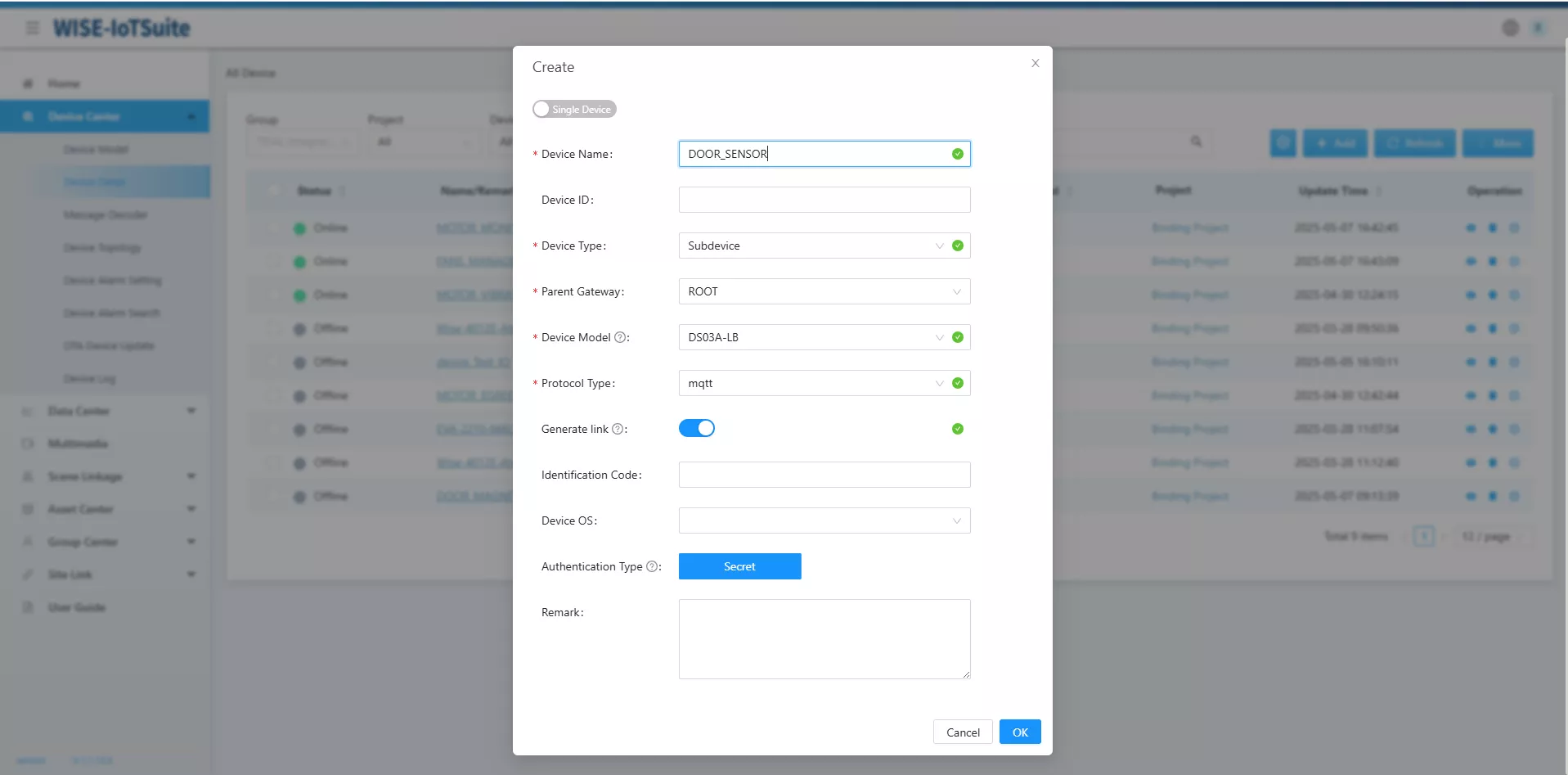
Note: please make sure to check the Generate Link option when creating. This option allows you to generate unique MQTT identifiers for your device. You will then use them in the LoRaWan gateway to ensure the security of exchanges with IoTEdge
Once the Device Detail is created, it will appear in the list of devices. Click on its name to access its detailed settings.
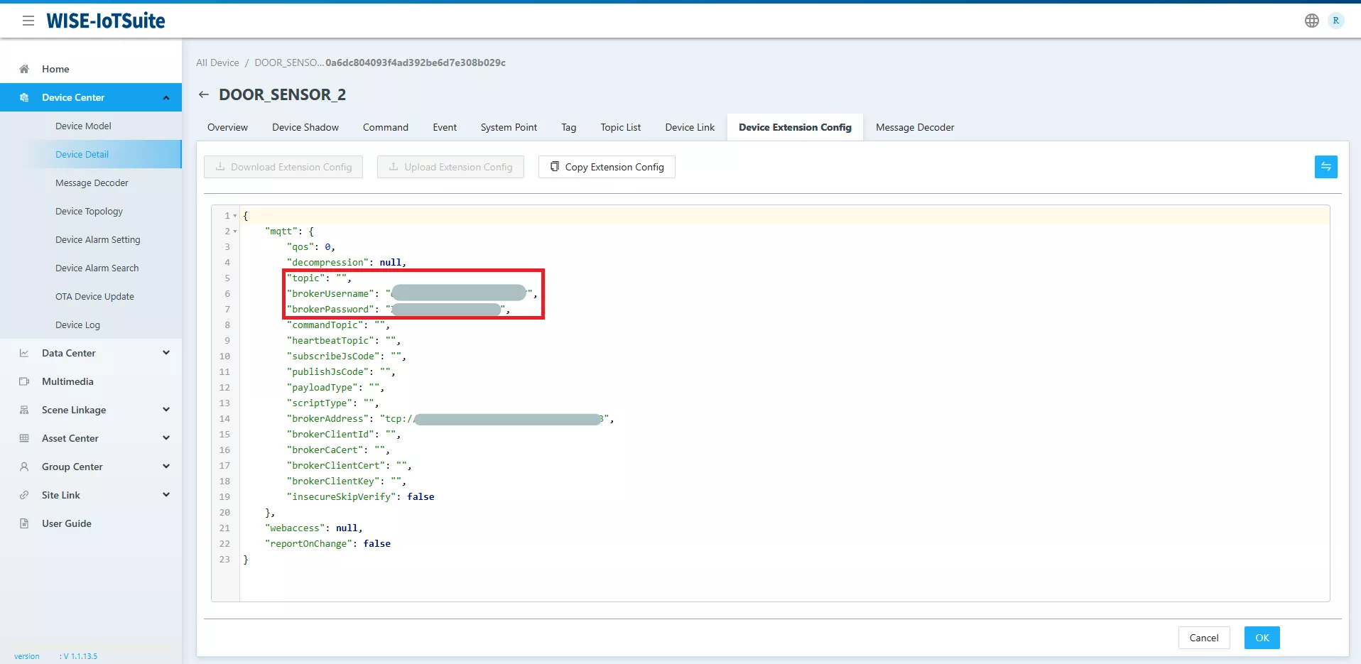
In the Device Extension Config section, note the following information, necessary for MQTT configuration:
In the Device Extension Config section, note the following information, necessary for MQTT configuration:
- brokerUsername
- brokerPassword
Also take this opportunity to define the topic field, by entering the desired MQTT topic (for example: data).
This information will allow you to finalize the configuration of the Node-RED flow of the gateway.
Before that, it is necessary to associate the custom conversion script with the Device Detail. This script allows IoTEdge to decrypt the JSON data format defined earlier in our Node-RED flow.
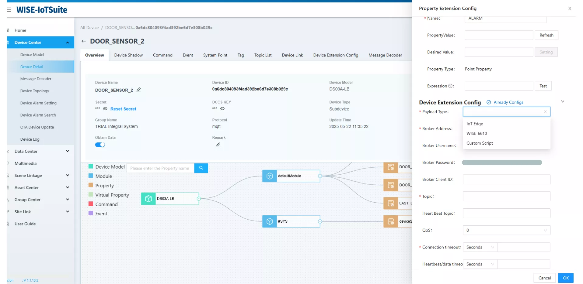
Start by copying the Device ID of the device, then go to the Overview tab. Open the settings of one of the variables, then in the Device Extension Config section, change the Payload Type field by selecting Custom Script.
Before that, it is necessary to associate the custom conversion script with the Device Detail. This script allows IoTEdge to decrypt the JSON data format defined earlier in our Node-RED flow.
Start by copying the Device ID of the device, then go to the Overview tab. Open the settings of one of the variables, then in the Device Extension Config section, change the Payload Type field by selecting Custom Script.
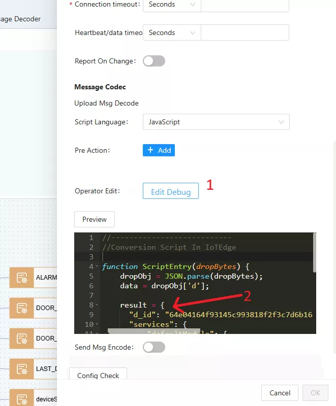
Further down in the Message Codec section (see illustration on the right):
- Click the Edit Debug button (1) to open the script editor.
- Replace the existing content with your conversion script.
- Make sure to modify line 9 of the script by replacing the default value of d_id with your device's identifier (2).
Finally, you just need to enter the MQTT broker credentials obtained earlier in the NodeRED flow that we had pre-configured in the gateway.
Physical installation of the sensor
During testing in a test environment, the sensor was activated by bringing the two magnets directly into contact. However, in the context of the final installation, these magnets will not be in direct contact. It is therefore essential to determine the distance at which the sensor switches from one state to another.
Manual measurements showed that the state change occurs at about 3 centimeters apart between the magnets. This distance may vary slightly depending on the opening speed.
Although this parameter does not present a constraint in our case, it is important to consider it in more sensitive installation contexts.
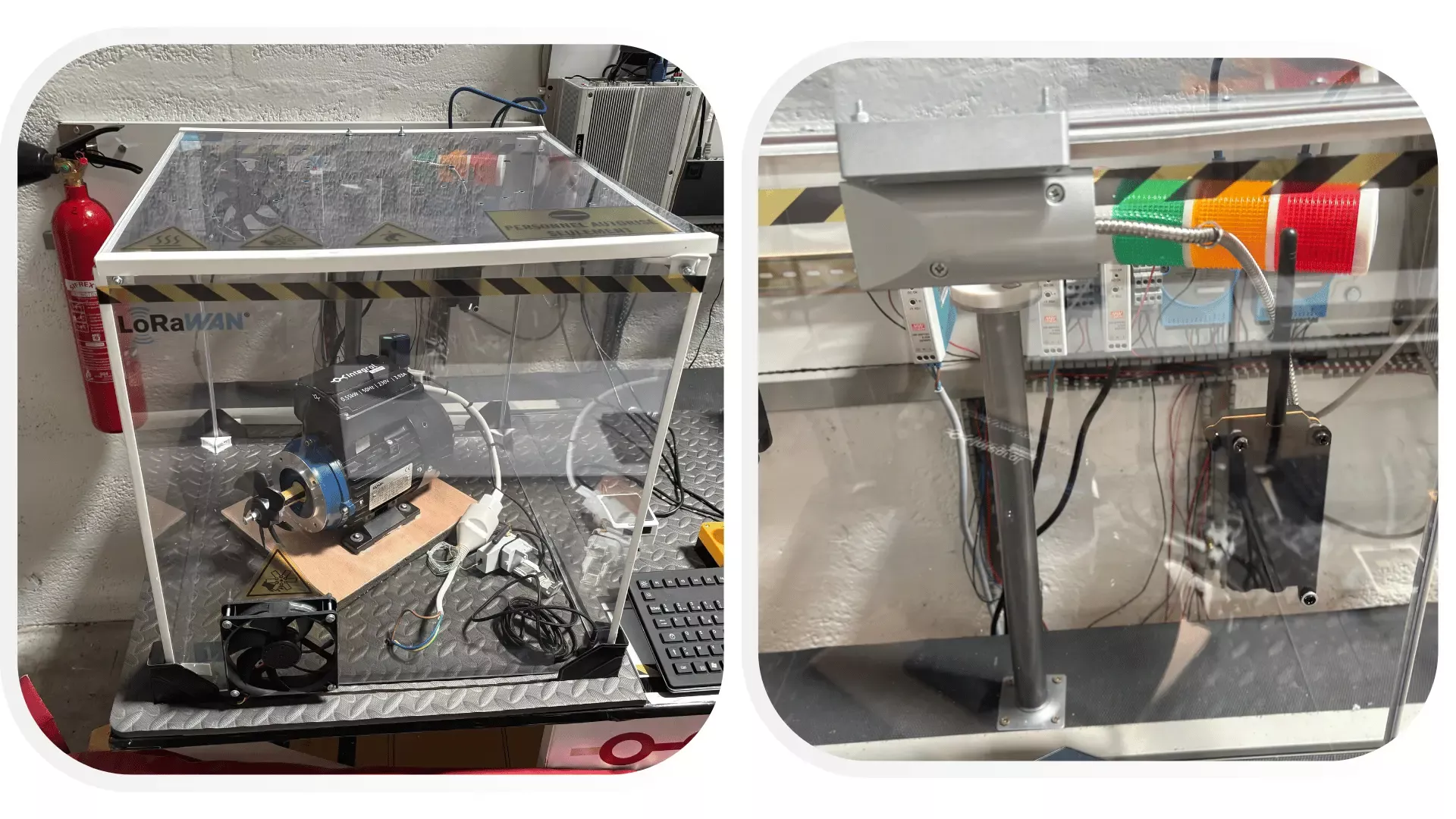
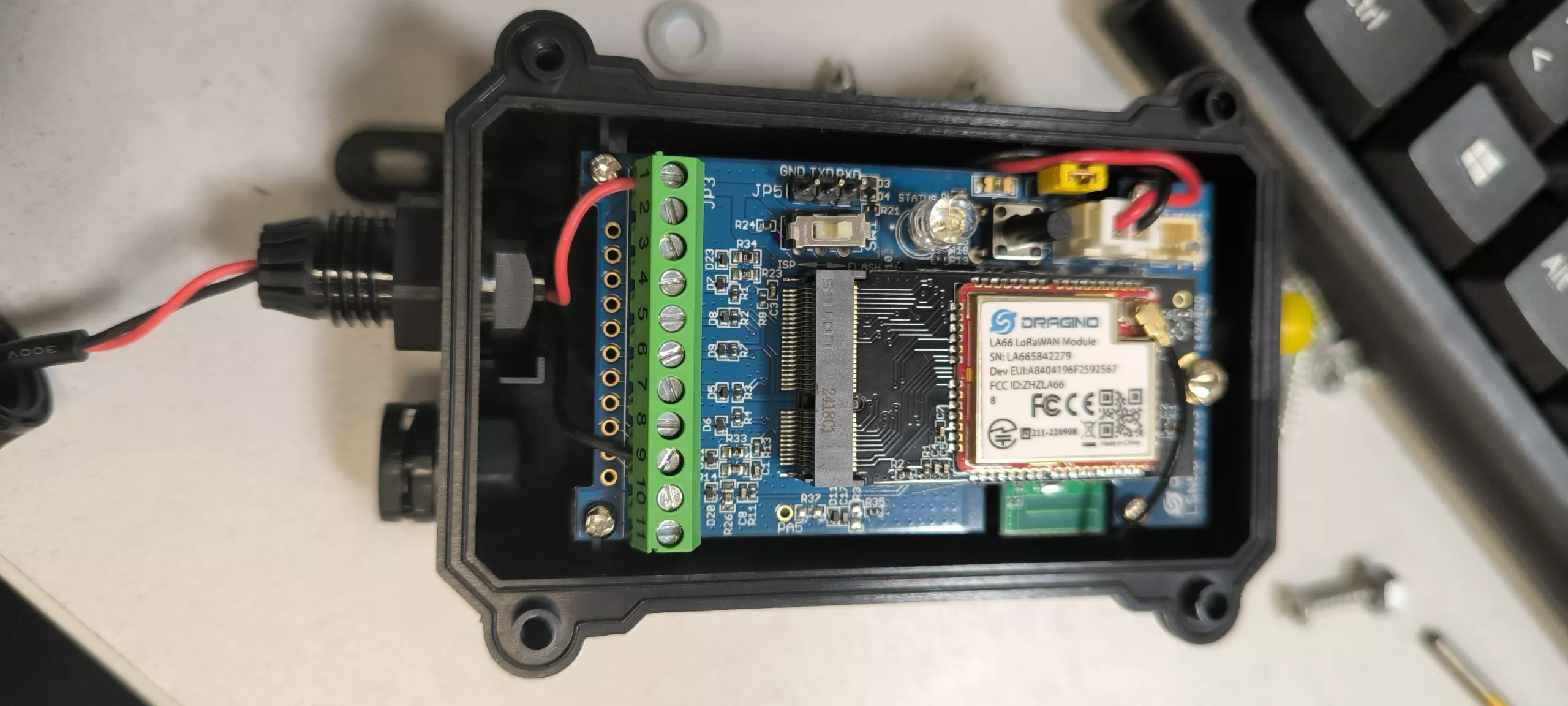
The two magnets of the sensor can be placed inside the test block. However, it is preferable to install the sensor outside.
To do this, it is necessary to detach the magnetic part from the main housing, attach it to the inside of the cube, and then pass the connecting cable through a hole drilled in the wall.
When reassembling the sensor, it is essential to reconnect the wires of the magnet correctly. By default, the red cable should be connected to terminal 1, and the black cable to terminal 9.
Part 2 of this article is currently being drafted.
Detailed articles
Discover our detailed articles
At the heart of our expertise and know-how, we share detailed articles on the topics that shape our daily lives.